Ethernet transceiver
December 6, 2022
My discrete computer lacks two major things: sound and network. The project I describe here is the first step to making it capable of network communication. I don’t touch the computer itself now, but instead build a transceiver which converts a 10BASE-T Ethernet signal to SPI and back. I use an STM32 MCU to test my transceiver for now. In the future I plan to connect the transceiver to the discrete computer.
Ethernet operation briefly #
10BASE-T uses two differential pairs: one for transmission and one for reception. Each pair is coupled through a transformer.
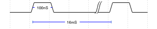
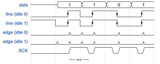
The signal is differential and Manchester-encoded. When idle, a network device must send normal link pulses (NLP): 100 ns positive pulse every 16 ms. These pulses let the other side know that something is connected to the port.
Ethernet data comes in frames. Each frame starts with a fixed synchronization preamble and ends with a frame check sequence (FCS). The synchronization sequence consists of 62 alternating ones and zeroes and finally two ones. Each byte in the frame is transmitted LSB-first.

Receiver #
If you look at a Manchester-encoded signal, you can see that the data is already there. The current bit’s value is present on the line right after the mid-bit transition.

To construct an SPI signal from that, it’s enough “just” to generate a clock signal, the low-to-high transitions of which will be used to latch a bit from the original Manchester-encoded line.

Clock generation #
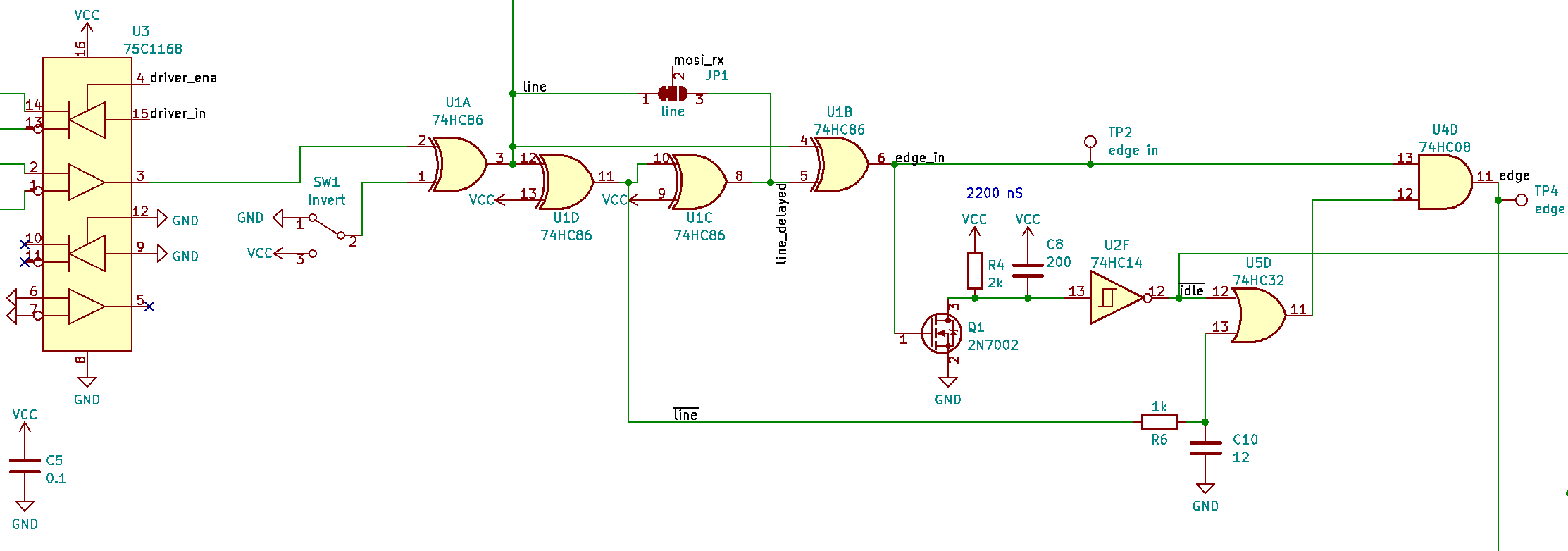
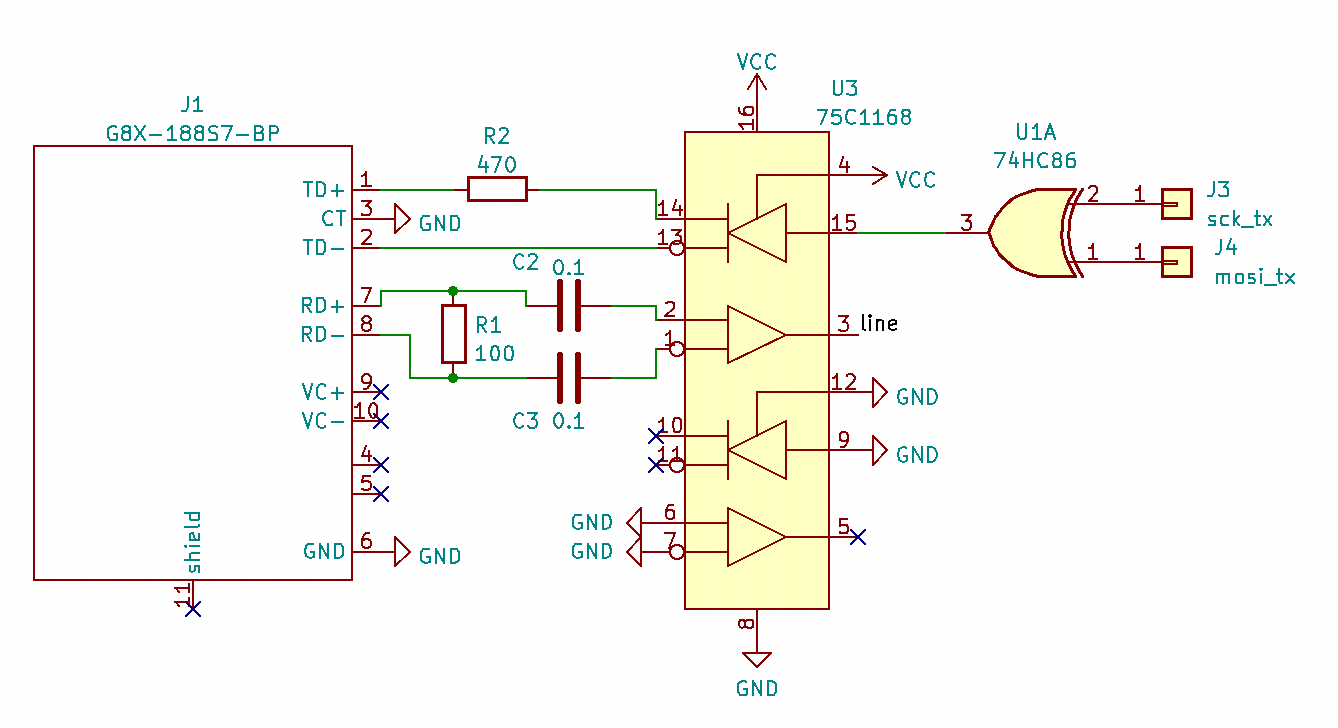
When researching for this project, I found this blog post. Its author uses a 75c1168 chip to convert the differential 10BASE-T signal into usual 5V logic levels and then detects edges by XORing delayed signal with itself. I stole this part of the schematics from him:
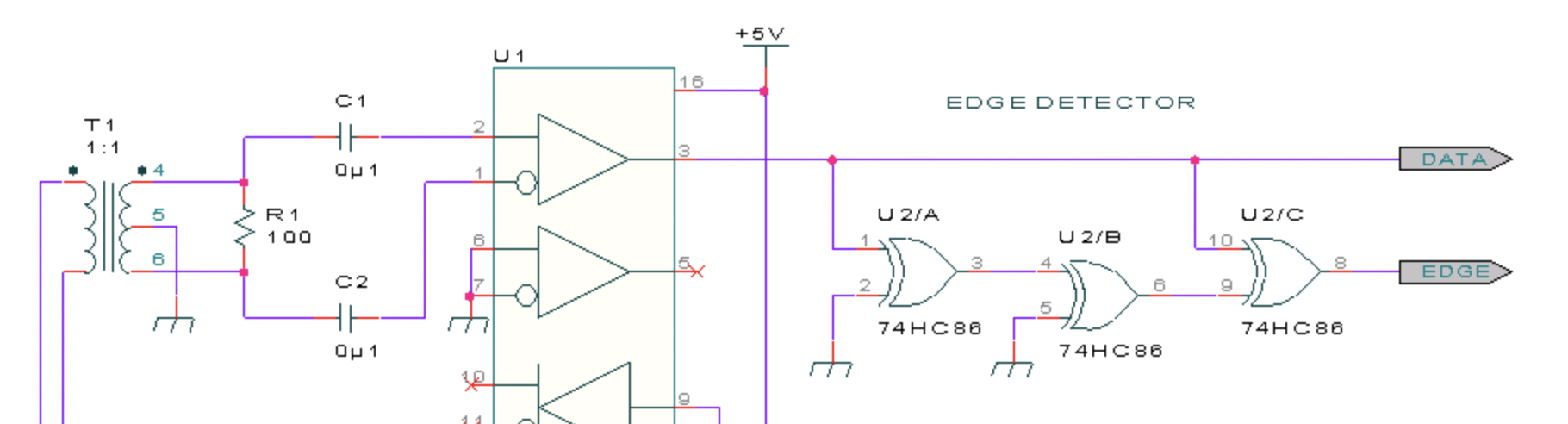
However, after edge detection Andrew (the author of the mentioned post) casts some complicated PLL magic which is above my level. I decided to take an easier path. Having the base signal and its edges is almost enough for SPI: we could latch the bit using the edge signal. This signal already provides positive transitions in the right spots, but the problem is that sometimes extra pulses come between the ones we want to use as clock:

My idea was to filter the extra edges out by a monostable non-retriggerable circuit. The circuit will trigger on the first edge and produce a pulse of approximately 75 ns. During that time another edge may come, but it will be ignored by the circuit. This new signal can be used as an SPI CLK now.
The monostable edge filter is built around an RC circuit and some invertors.
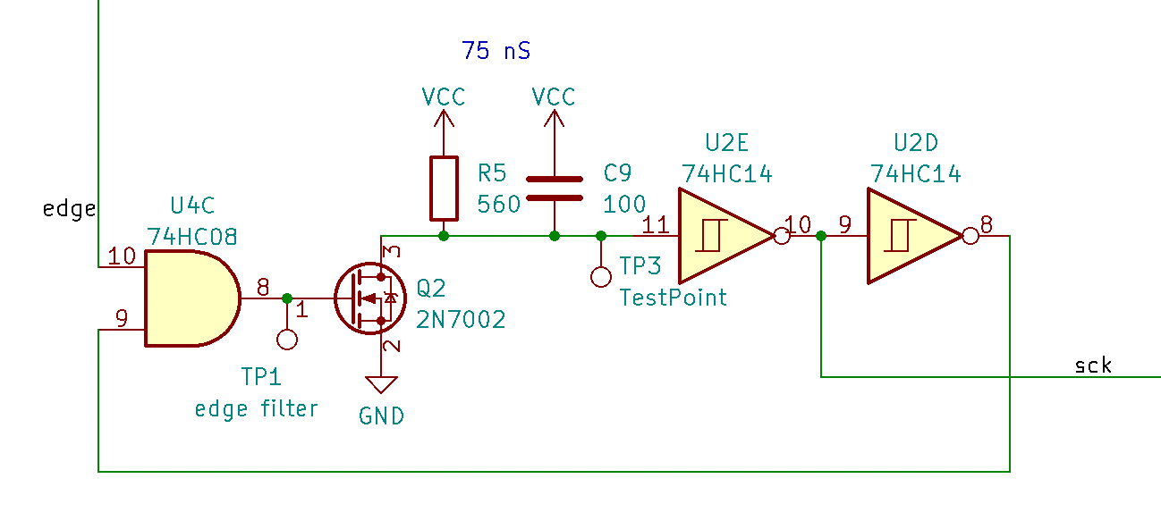
In an idle state edge is zero, which makes the AND gate U4C output zero. Q2 is closed and R5 pulls U2E input high. This high logic value, twice inverted, goes back to the other input of U4C. When edge goes high, the output of U4C goes up and opens the transistor. The capacitor is quickly discharged, driving U2E’s input low. This propagates back to U4C, switching its output back to low. Q2 closes, C9 starts to charge through R5. During this slow charge time the feedback signal remains low and keeps further edges from propagating through the AND gate.
Frame detection #
When the signal on the line becomes still the reception of an Ethernet frame should be considered complete. To detect that I use another monostable circuit (this time, retriggerable) which triggers on any edge.
Here on a high level on edge_in the transistor opens and quickly discharges the capacitor, which drives the U2F output high. This output only goes low when there is no edge for about 2 µs, which indicates an idle state.
Switch SW1 is used to invert received signal because some routers apparently have their differential lines swapped.
First edge filtering #
When the RX line is idle and the voltage difference on the differential inputs of 75c1168 is close to zero, the differential amplifier output level is undefined according to its datasheet (can be either logic zero or one). The first bit of an Ethernet frame is always one, which means there might or might not be an extra edge in the beginning depending on the idle state of the amplifier. This extra edge, if it comes, needs to be filtered out.
This filtering is done with gates U5D and U4D together with R6-C10 network. U4D lets the signal through only if the value on line a moment ago (delayed by R6-C12) was low or (U5D) if there has already been an edge. I didn’t have a chance to test this with idle zero, because in my case the idle value on 75c1168’s output is always high.
Result #
Here is how the generated clock signal looks on the oscilloscope:
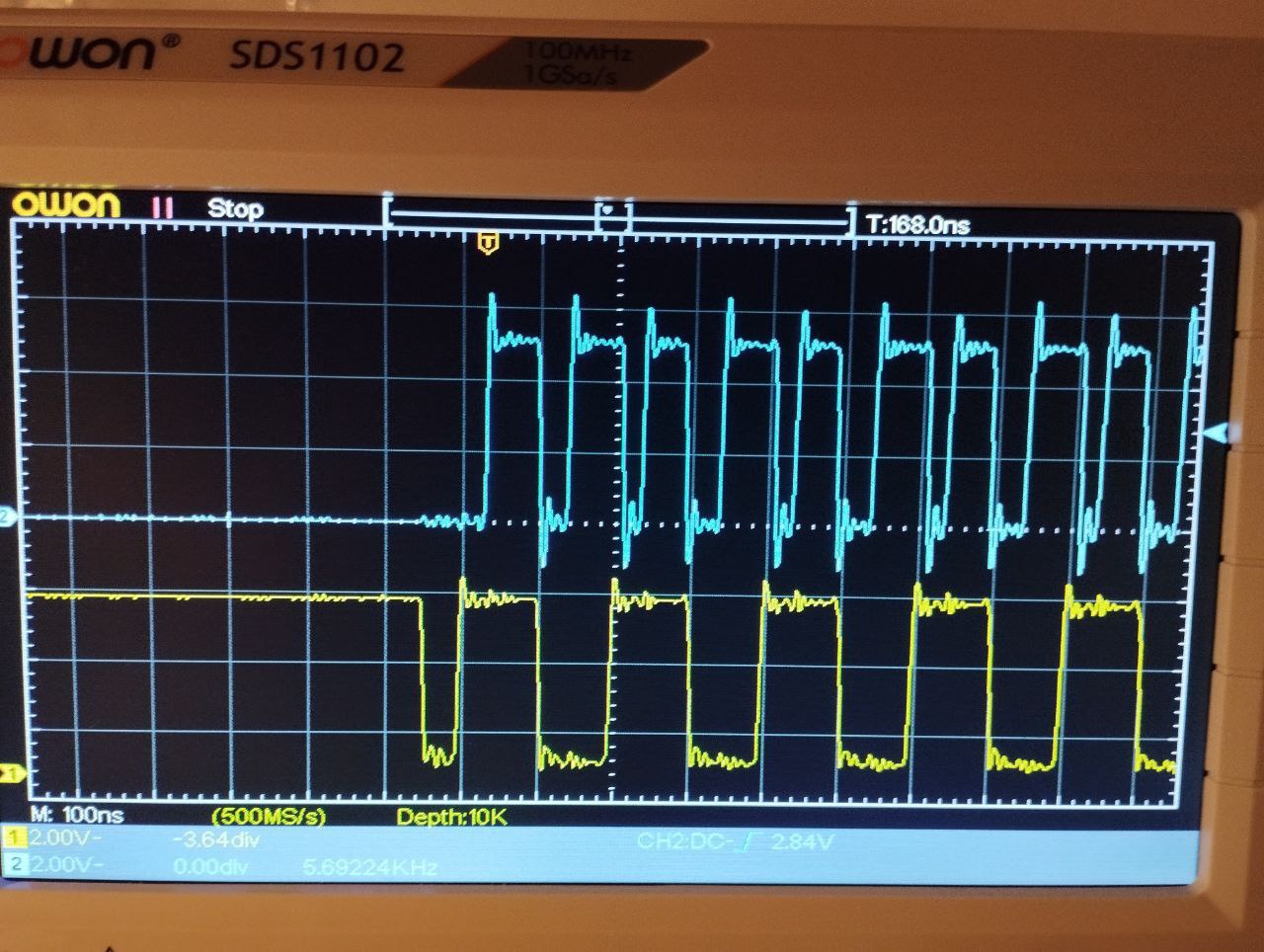 Yellow is the differential amplifier output, blue is the generated clock signal.
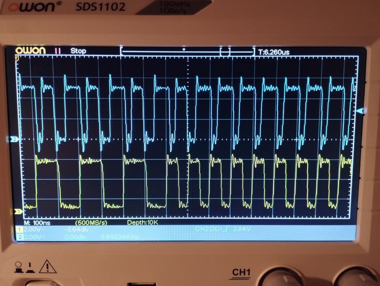
The clock signal doesn’t look really precise, but its only important property holds: its positive edge always indicates a data bit on the input line.
And this is how the first prototype of the receiver looked like:
Synchronizing #
According to the 10BASE-T spec, each frame starts with a fixed synchronization sequence of 64 bits, first 62 of which are alternating ones and zeroes and the last two are ones. However, some hardware I have sometimes produced longer preambles. As a workaround, I added the following circuit:
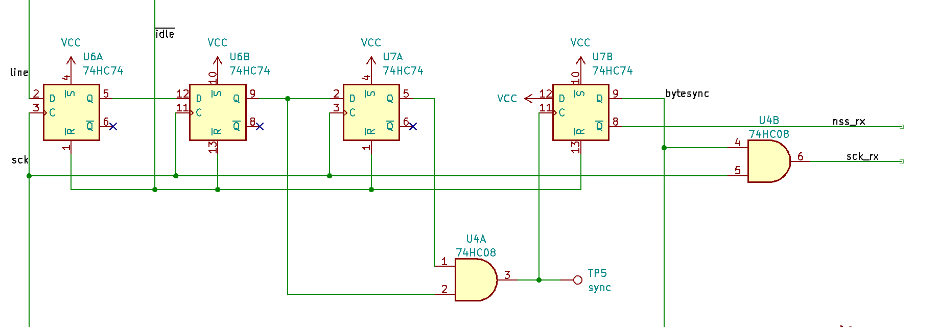
The first three flip-flops make a 3-bit shift register which shifts input bits into itself. The last flip-flop latches a logic one when the last two shifted bits were both ones. Its output is used to filter the clock pulses during the preamble and as the slave select signal for the SPI.
Transmitter #
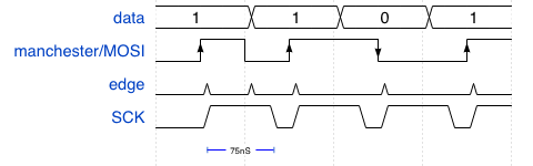
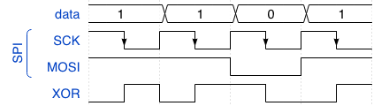
A Manchester-encoded signal is just an XOR of SPI signals SCK and MOSI:
It being that simple, I didn’t pay much attention to implementing it in hardware and in the first version just fed both SPI and MOSI lines through an XOR gate to the always-on output amplifier.
When I used this schematic and generated the NLP pulse in software, the connection was not stable at all. Most of the hardware I have couldn’t recognize the connection and the few devices that could did that unreliably. I suspected that the timings of the NLP were not precise enough and switched to generating it with the following circuit:
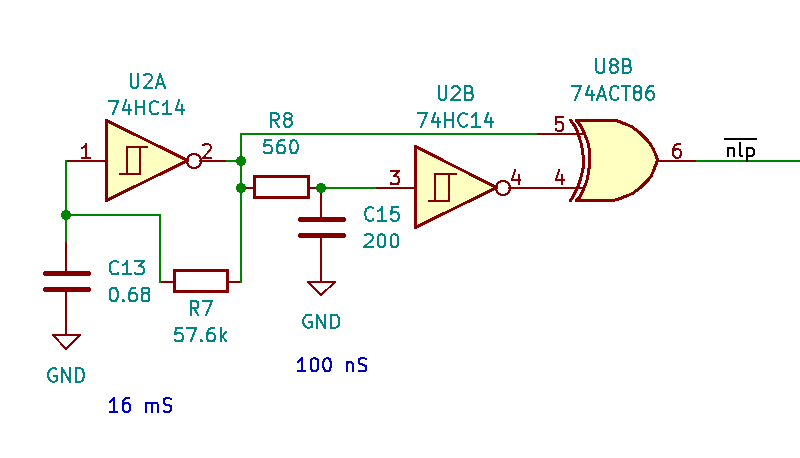
Here U2A, R7 and C13 form a square wave generator with a period of approximately 32 ms. Then, R8 and C15 delay this signal by 100 ns. The XOR gate produces negative pulses when the delayed inverted signal matches with its original. This happens for 100 ns every 16 ms, which is the requirement for NLP.
With the hardware NLP generator the connections became more stable, but still my network adapter was recognized only by few network devices I had and not recognized at all by the most. I realized that the NLP pulse doesn’t have the correct form: it must be a positive-only pulse, but in my case it briefly switched polarity back and forth:
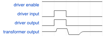
This happened because the output driver was always on and produced either positive or negative voltage difference on its output terminals. After a positive pulse a negative state followed which was transformed into a negative pulse by the output transformer.
I had to make use of the Enable signal of the differential driver.
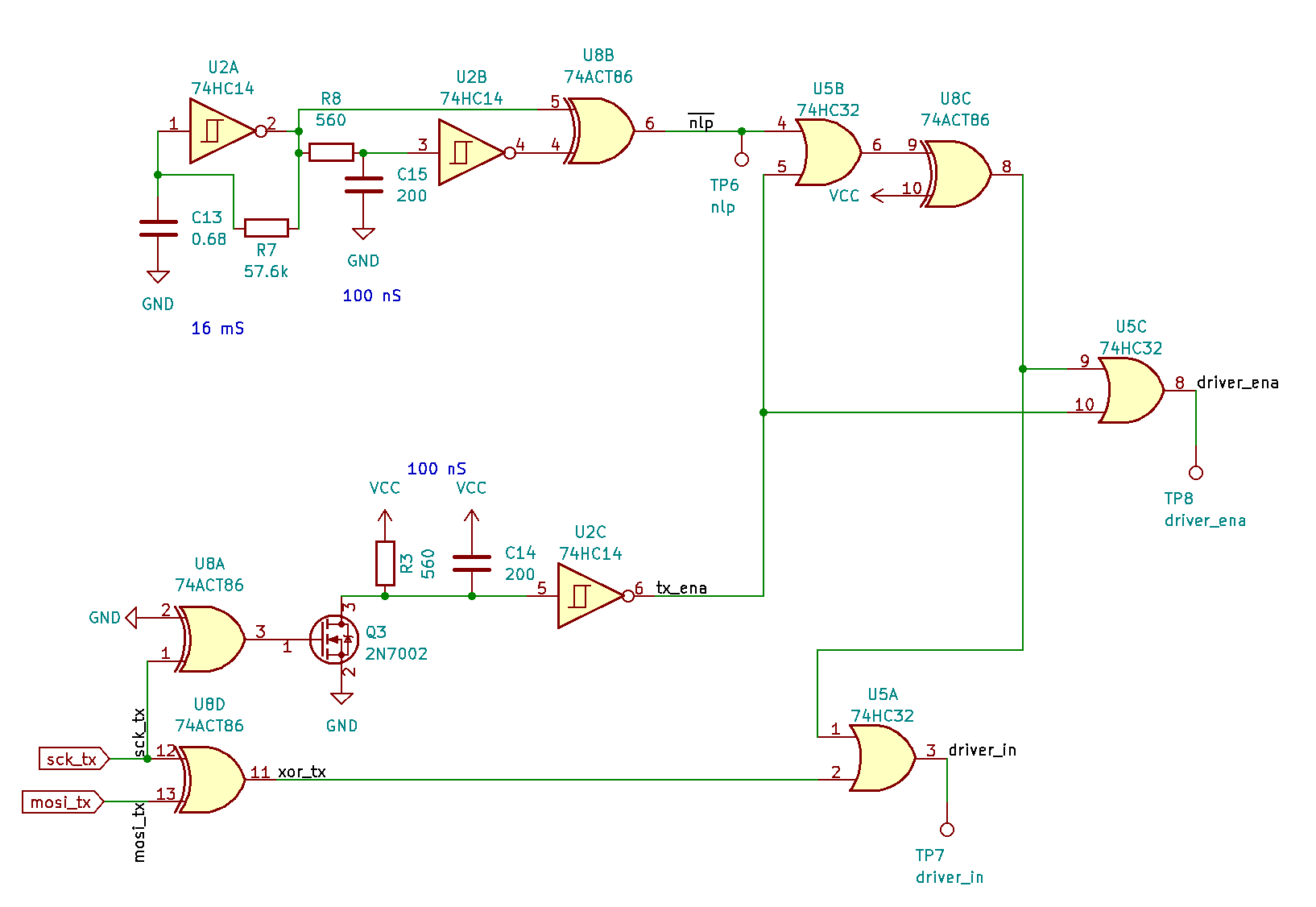
Here driver_ena and driver_in go to the differential driver (not shown). U8D converts the SPI signal to Manchester coding. Q3 and U2C form a retriggerable monostable circuit which produces a signal to enable the output driver during frame transmission. The same signal is used to suppress the NLP when a frame is being transmitted. U8A is used as a buffer to prevent the Q3’s gate capacitance from introducing a delay to the input clock line. Such a delay would shift SCK relative to MOSI and spoil the Manchester signal.
This transmitter works almost flawlessly, but there still remains one router which doesn’t recognize it.
The MCU part #
The counterpart for my adapter must be capable of sending and receiving SPI data at 10 MHz rate. A stm32f100 microcontroller I had on a development board matched this criteria. Using built-in DMA with SPI I was able to send and transmit frames.
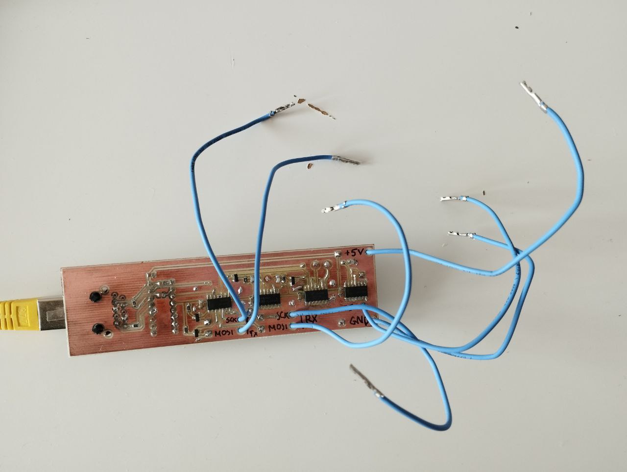
 This is how my prototype looked like when I already had a hardware NLP generator (smaller board), but didn’t have a byte synchronization module. The gray box is a UART adapter used to get debug traces.
Using smoltcp I was able to have my board get an IP address using DHCP, answer pings and even serve an HTTP page. But the stm32f100 MCU had barely enough RAM (8 kB) for all the buffers I needed. Luckily I got my hands on another development board which has an stm32f401 with 96 kB of RAM on it.
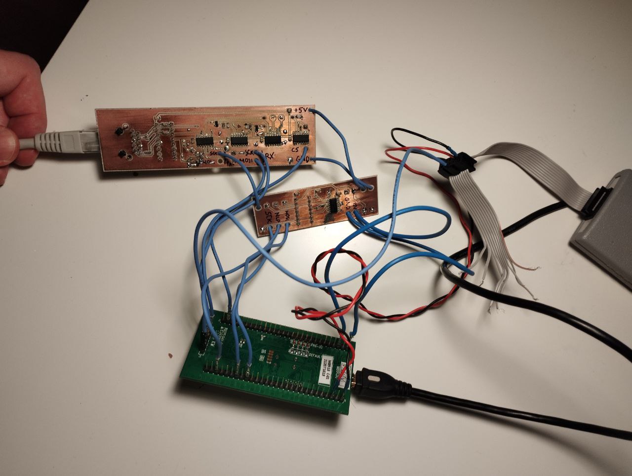
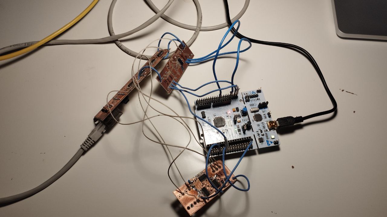 Latest prototype with three custom boards (receiver, transmitter/NLP generator, and byte synchronizer).
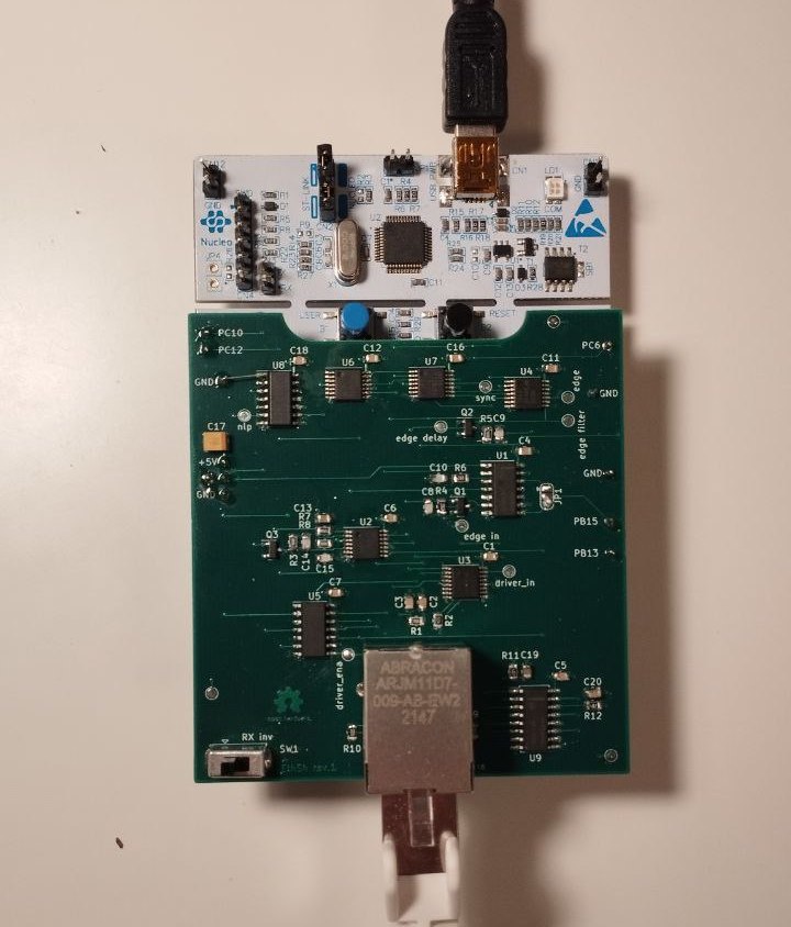
Having almost all problems fixed, I ordered the final PCB in China. The connector on the board matches the ST Morpho connector on the Nucleo-64 board and can be installed a shield.
With 96 kB of RAM I could even use TLS (with embedded-tls). I used TLS to make a simple Telegram bot which echoes a message and notifies you when a button is pressed on the board.
Ways to improve and further steps #
Currently when exchanging heavy TLS traffic a lot of frames are lost because the receiver buffer isn’t re-armed quickly enough after receiving a frame. This is okay though because TCP is pretty robust, but fixing it will improve the bot’s performance.
My further plan is to build a hardware module for the discrete computer which will use this adapter to send and receive Ethernet frames. The module must be capable of filtering frames by destination MAC-address and rejecting frames with invalid checksum.
Project repository #
Schematic files, PCB drawings and the firmware is located on github.